Teaching machines to draw
November 28, 2017
Turns out my steppers and drivers worked just fine, I just didn't have enough voltage. 9V battery does the trick. I also found out my first EasyDriver is in fact perfectly fine, which is good news.
October 3, 2017
Managed to solder pins on my EasyDrivers, they fit nicely into the breadboards now. Hopefully I didn't cook any of the components.
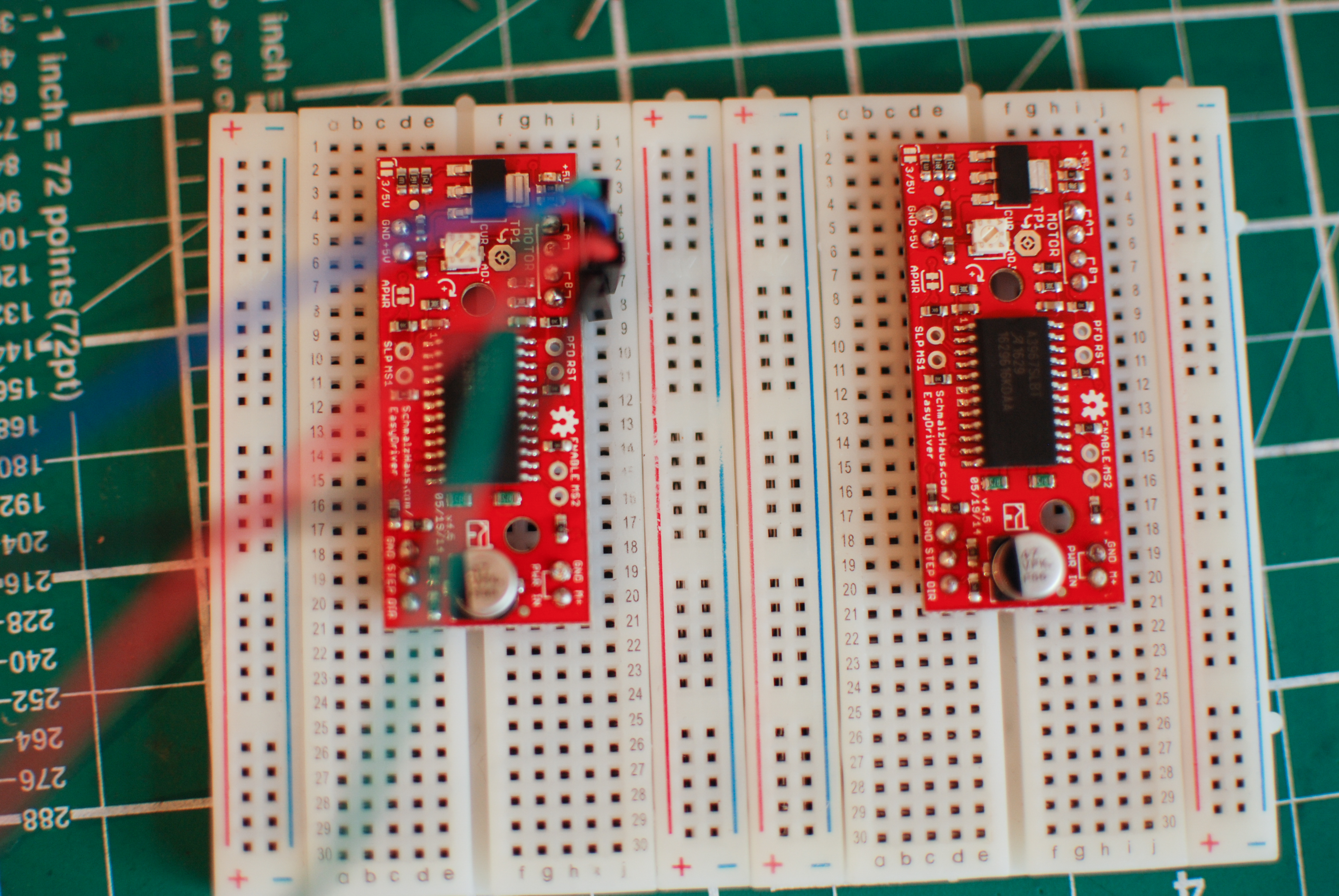 BA Graphic Design level soldering
October 15, 2017
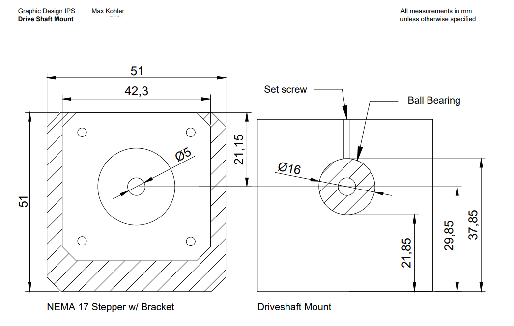
I found out you can get AutoCAD for free as a student, so I used that to draw up the shaft supports I need to build. What a good piece of software. (I can't believe I ever thought it was a good idea to do this in Illustrator)
October 17
Bought some more components to help with the wood:
- 1 x 16mm Auger bit (To drill a hole that will take a ball bearing)
- 1 x 8mm General purpose bit (to make supports for the slide shafts)
- Mounting brackets
- Machine screws
October 18, 2017
Had a good talk with a technician at Camberwell today concerning cutting my MDF (shouldn't be a problem) and drilling holes for my shaft supports (might be a problem). Turns out the 40cm drill bit I bought yesterday is going to be useless - you can chuck it in a drill press, but because it's so long it will wobble and make it impossible to drill a precise hole. The workshop has some special drill router bits that should work better.
Cutting the 5mm steel rod isn't a problem, he says. I'm starting to think having two shafts at the end might be useful, it allows me to tighten each timing belt seperately (but then again I'm increasing friection and I could probably cut both belts to the same lengths with reasonable precision)
Workshops are closed Wednesday afternoons, and they're doing inductions Thursday - So I'll be cutting my MDF Friday afternoon.
Also I held some screws up agains things and found out that I do have the correct machine screws to go in my linear bearings, and my wood screws will fit in my angle brackets.
October 20, 2017
Got my MDF cut to size - turns out I couldn't get 15 pieces because you loose 3mm with each cut (the width of the saw blade). I managed to put together a version of the slide mechanism using MDF blocks and mounting brackets.
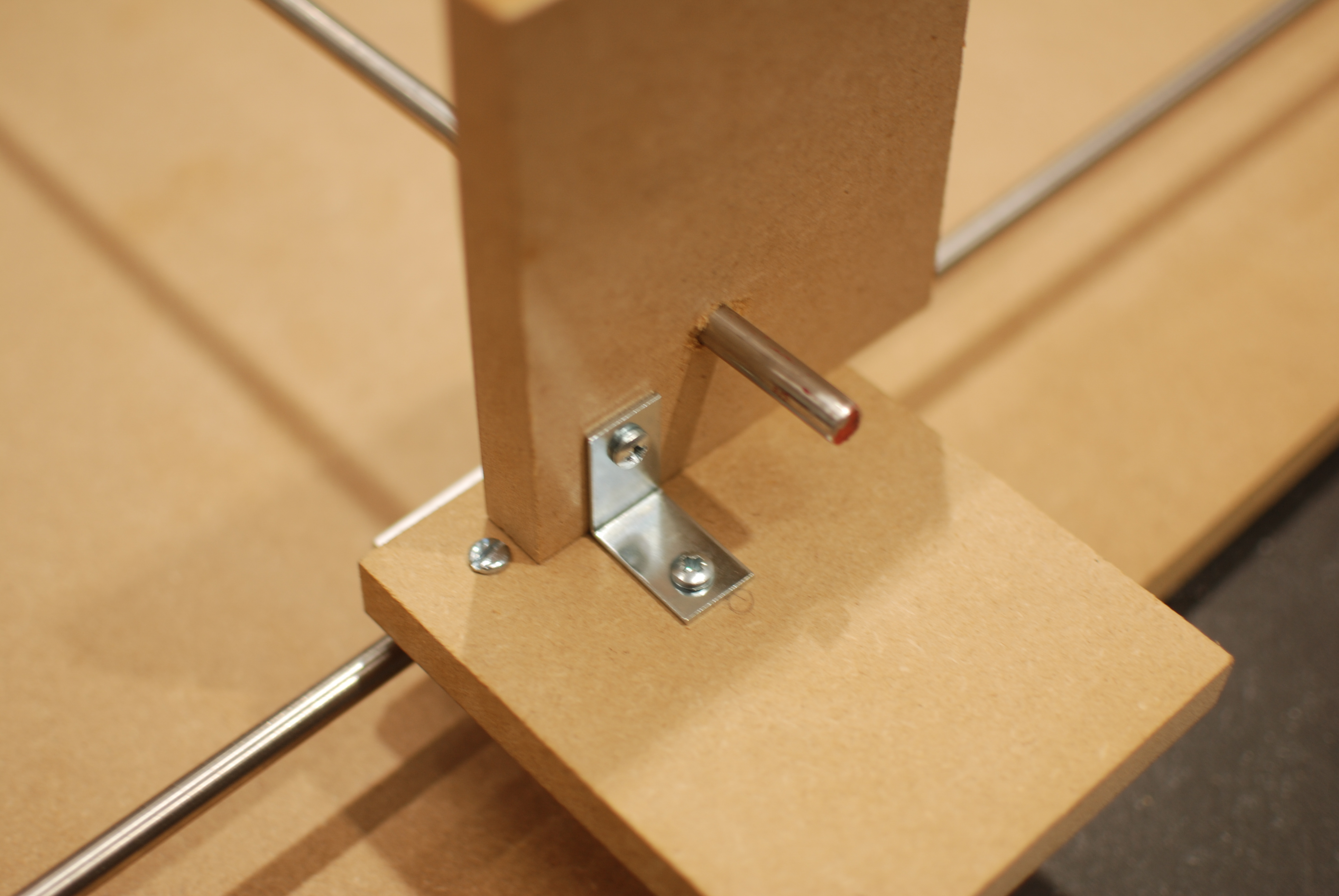
Because the rods are so long, there is quite a lot of springy-ness to them - hoping this won't be too much of a problem since there isn't going to be much weight on them.
Problems:
- It's difficult to get the MDF blocks to sit straight using mounting brackets - it always pulls them in one direction or the other
- MDF doesn't work too well as a shaft support - the rods move around in the holes, causing the slide to get stuck.
I've ordered some machine-made aluminium shaft supports which should solve both problems at the same time.
Hoping to install the drive shaft (with temporary support) and do a test with the motor by the end of next week.
October 25, 2017
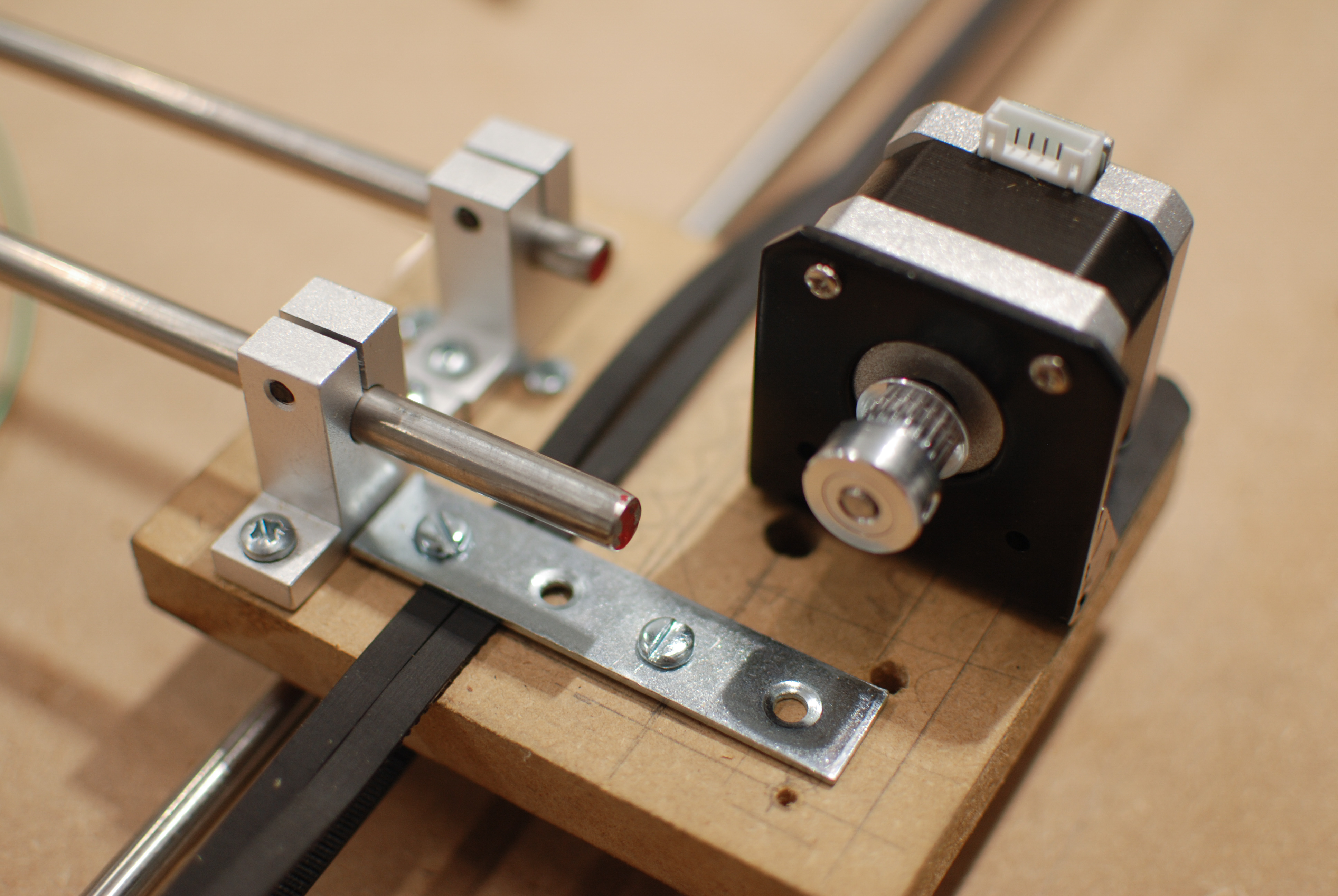
The aluminium shaft supports arrived:
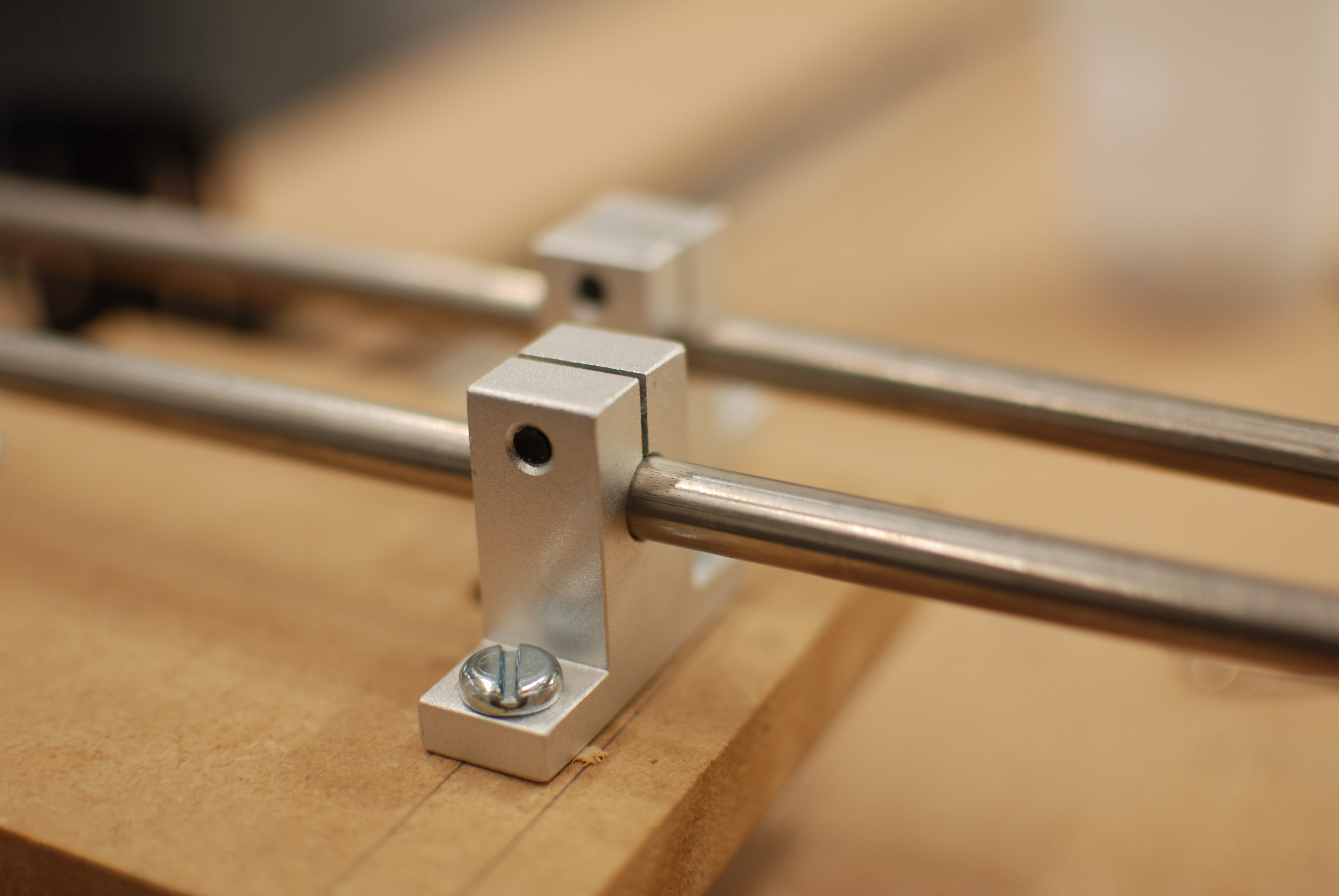
With them installed, everything seems much more stable. There's also the added benefit that the slide sits much lower over the table surface, which means the eventual pen won't be too far from the paper. The aluminium supports are also much lighter than the MDF ones. Still, the slide doesn't run perfectly smooth, but I'm hoping some small adjustments and a bit of oil will solve that.
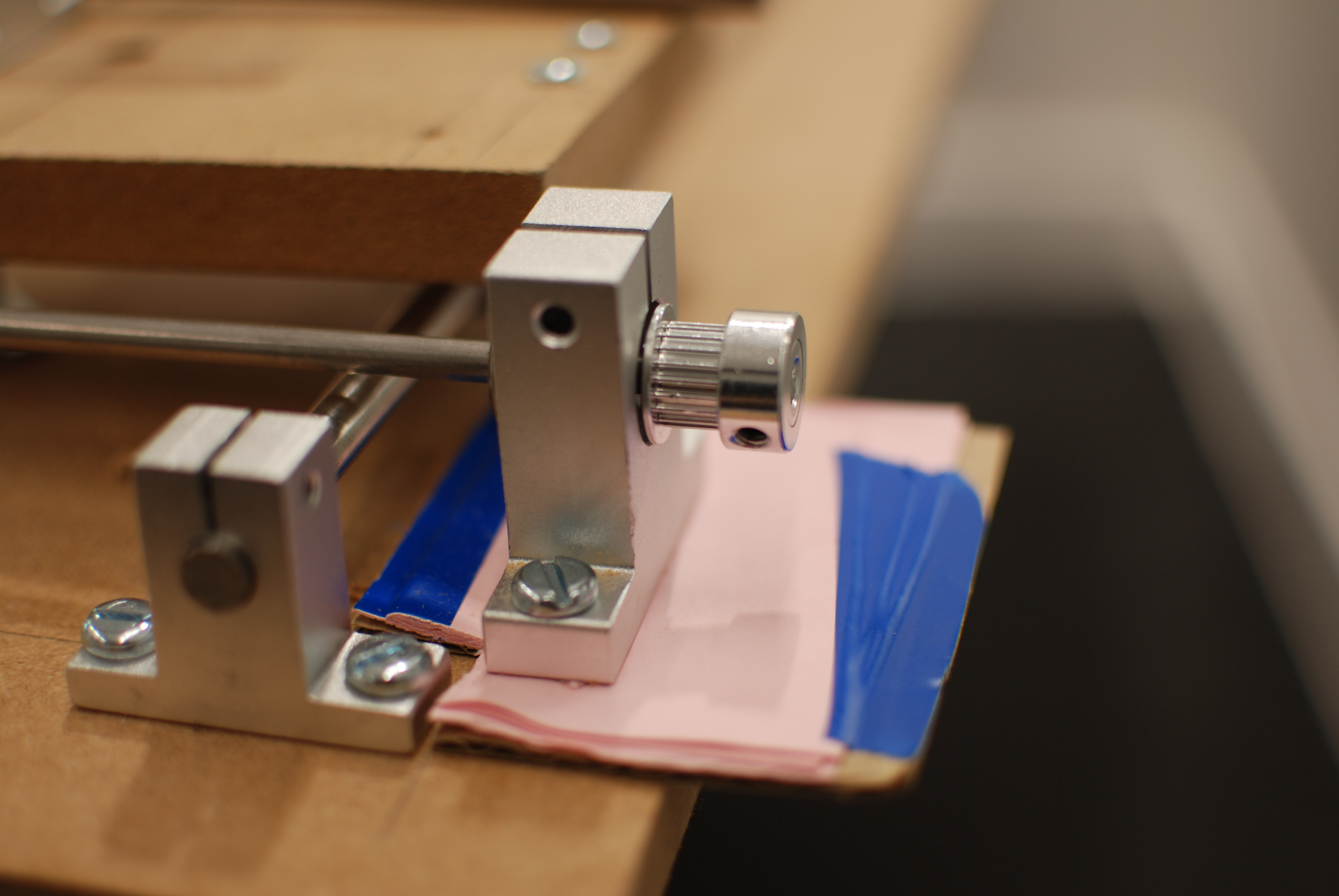
Following my disillusionment with the MDF shaft supports, I got an aluminium part to take the driveshaft. A few layers of paper to bring it to the height of the motor shaft.
I came up with this arrangement to mount the timing belts:
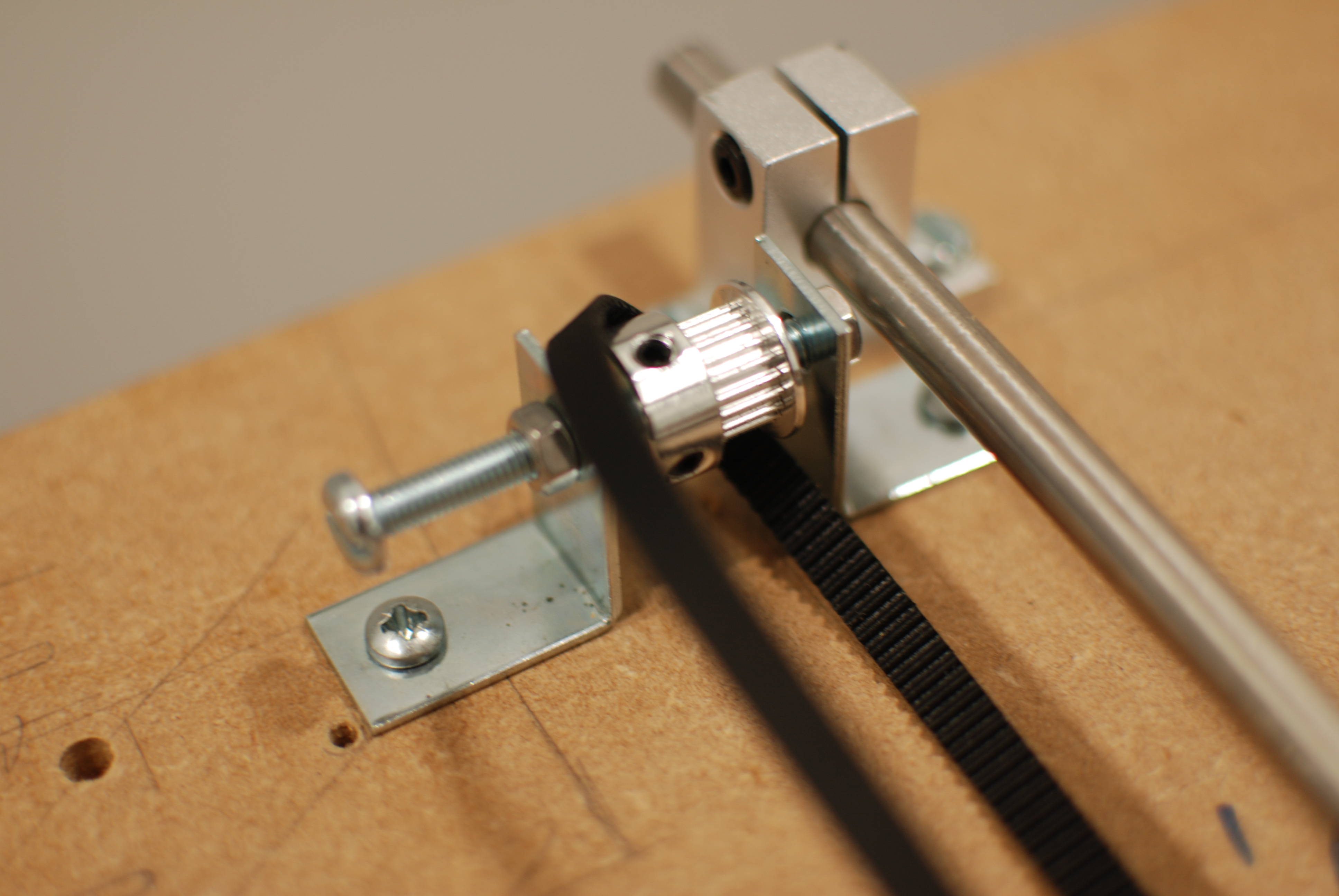
It consists of two corner braces, an M5 screw and some nuts, all of which I had already. However I doubt this will be stable enough to support the belt once it's under tension.
I'm mounting the belt as close to the linear bearing as possible, so there's the least amount of leverage to get it stuck.
October 31, 2017
I came up with this arrangement to attach the sliding platform to the timing belt:
It's a mending plate mounted to the slide with two M4 screws. The belt is squeezed between it and the platform - originally I was going to use two plates below the platform, but this is simpler and has the added benefit of holding the belt up (which means it needs less tension). This way I don't need to worry about trying to join the two ends of the belt together. I can also adjust the tension when I need to.
I repeated this on both sides, connected by the driveshaft. I then connected the stepper (happy to report the EasyDriver survived my soldering) and it works!
It's moving very slowly at the moment, but I should be able to fix that by going from 1/8 microstepping to 1/4 or 1/2 - effectively reducing the resolution by half and doubling the speed. The EasyDriver has two ports two do this which means I'll be able to adjust speed/resolution based on the drawing I'm trying to do.
Still missing a shaft support and stepper for the Y-axis.
November 2, 2017
I managed to double the speed of the slide using this logic table:
| MS1 | MS2 | Microstep Resolution |
|---|---|---|
| Low | Low | Full Step (2 Phase) |
| High | Low | Half Step |
| Low | High | Quarter Step |
| High | High | Eigth Step |
However apparently you get less torque the bigger the steps are? The lowest that would work reliably is quarter steps. This article would suggest it's way more complicated
I've also laid out the x-axis platform, which needs to fit a stepper, the belt attachment, two shaft supports and its own belt support. I'm running the belt in between the two bearings so it shouldn't get stuck. I've realised the pen should probably go between the bearings as well to reduce leverage that could twist the platform.
Ordered some wire to connect the second stepper once it arrives.
November 9, 2017
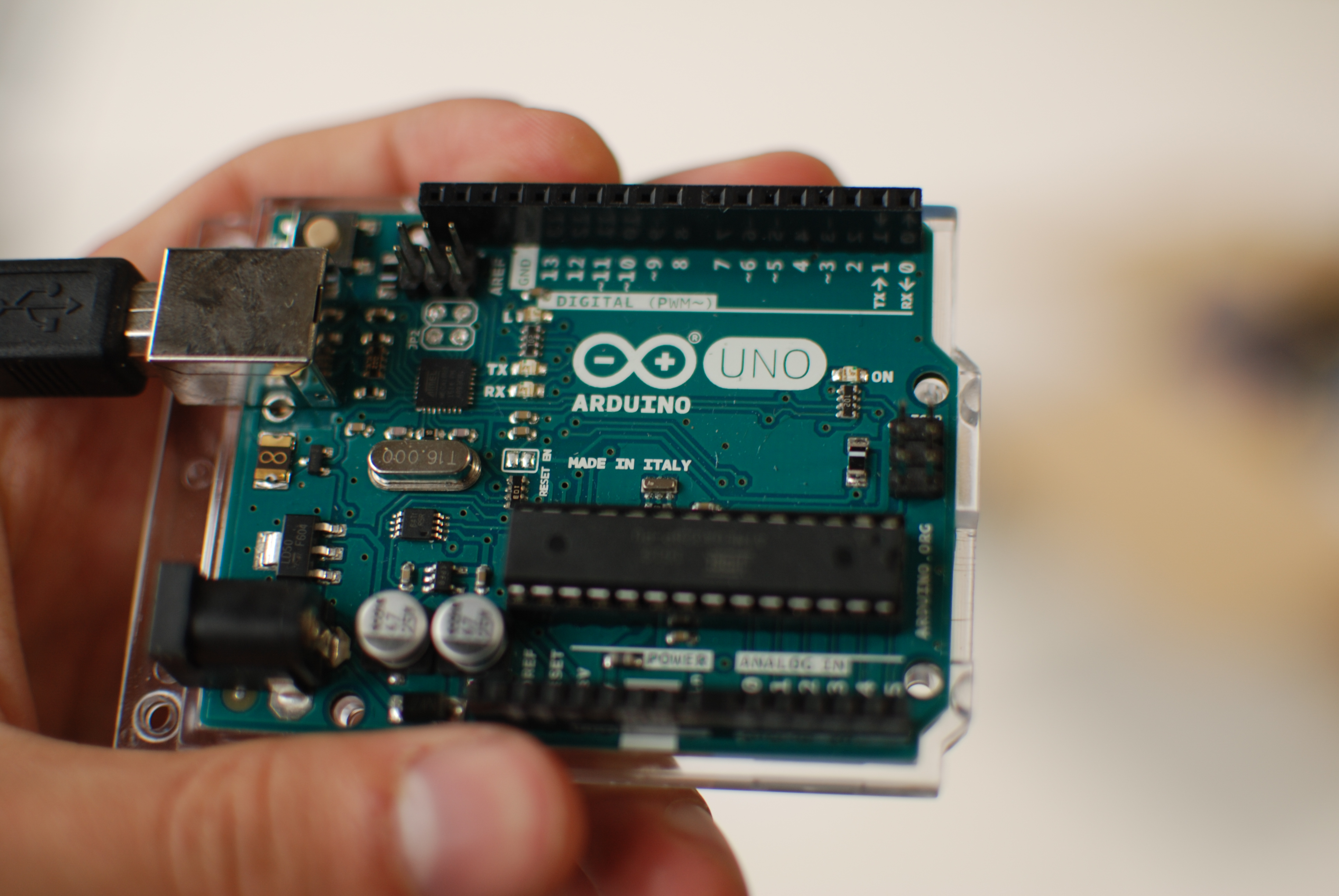
The stepper arrived, and it fits into the mount perfectly (thanks, National Electrical Manufacturers Association). Here's the full wiring setup with an Arduino, two EasyDrivers, and wires going off to the motors:
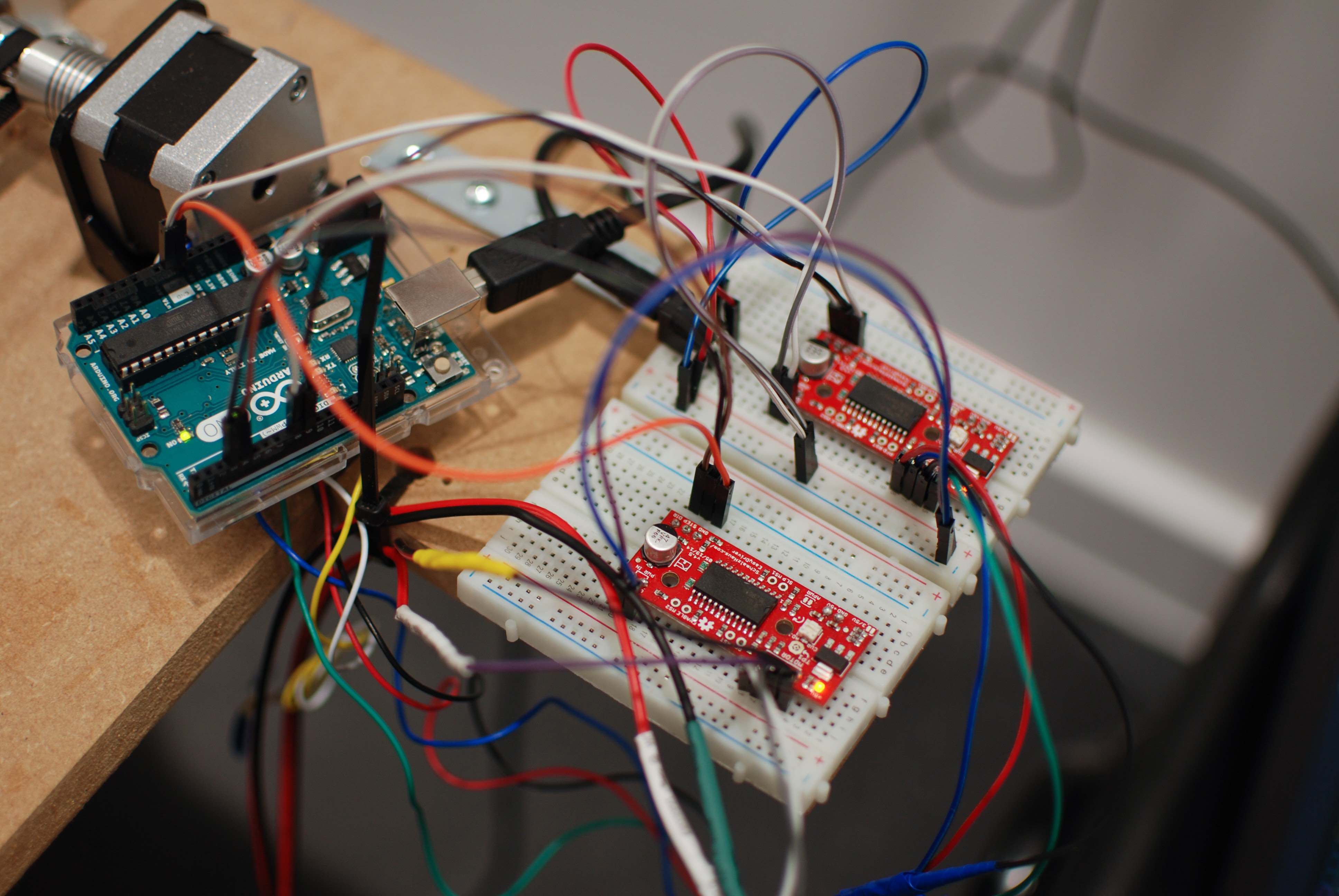
I wrote the most basic script to run the machine I could think of. Here's some pseudo code:
while i < 1000
    Set stepper one to direction 0 or 1
    Set stepper two to direction 0 or 1
    Do 500 steps on each stepper
    i++
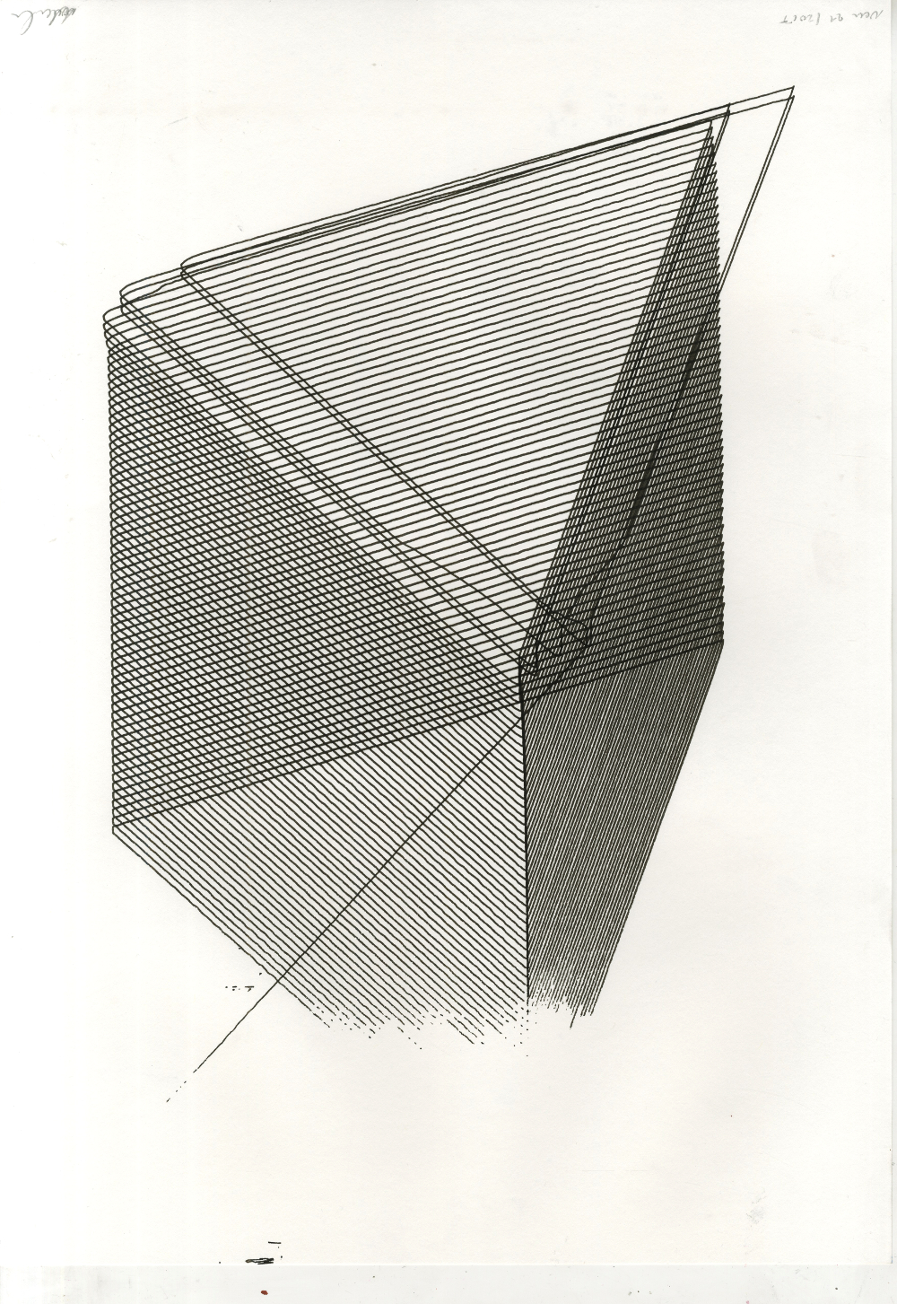
This draws a sort of diagonal grid - the very first work to come out of the drawing machine! Mostly this is a way to have the machine moving continuously so I can tinker with things.
The whole thing is quite wobbly, however some of this might be remedied when I find a beter way than masking tape to attach the pen to the drawing platform. Bringing the pen as close to the slide as possible should help: reduces the amount of leverage.
Tracey makes the point that the wobbly-ness might be part of the work: My individual handwriting is showing through me not being able to drill a hole in th right place. Though I'm hoping to get things at least a little more steady.
On the Y-axis I'm clearly running at the upper limit of torque that the stepper can put out. When there is two much resistance it gets stuck and makes an awful noise. The range of motion is limited by the belt going into a skewed angle, but it's still over a metre.
I have full range of motion on the X-Axis, which is about 90cm. Because the slide is much lighter and shorter (hence less tension on the belt) there aren't any torque issues.
November 10, 2017
Killed my laptop.
I made the mistake of messing with the wiring while the machine was running. I hadn't soldered pins onto the MS1 and MS2 switches on October 3, so I just stuck jumper wires through the holes into the breadboard. One of these came loose, and when I tried to put it back, my laptop went black.
My best guess is that I somehow made a short, which sent 12V from the motor circuit into the Arduino and my laptop's USB port. The laptop went dark immediately and wouldn't turn on anymore, needed professional repair: Wrong assumptions:
- The Arduino is idiot-proof. It's clearly not.
- 12V isn't enough to do any harm. It clearly is.
- Laptops have fuses in the usb ports. Maybe? My machine didn't need a board replacement, which indicates the 12V did get stopped somewhere.
I've bought something called a USB Isolator which is designed to prevent this exact thing from happening. It goes up to 30.000V - should do. Also not going to touch any wires while there's voltage on them again. I also put pins on the MS1 and 2 switches, so no more loose wires.
November 13, 2017
Tutorial w/ Tracey
November 15, 2017
Did some drawings using my freshly fixed laptop (Now being extra careful and using the USB isolator). I figured out a way to reduce the vibration in the machine: Waiting about 100ms between each command. slow things down, but the results are much nicer.
I took some measurements to work out how far the machine moves in a given number of steps. It's about 0.025mm per step (which seems way too precise, but I'm done messing with the microstepping resolution for the moment), or 40 steps in a millimeter. I got slightly different results for each axis (0.023mm/step on the x-axis). I'm assuming this is due to differences in the stepper motors (they come from different manufacturers) and inconsistencies in the overall construction of the machine.
Based on this data I expanded the driver code, so the machine is now aware of where it is at all times. This allows me to move the pen to any point on the table. By setting the two steppers to different speeds I can draw a straight line between arbitrary points. So far I've been using straight Javascript to make drawings - simple loops, random numbers etc. The next step will be to run SVG files through the machine.
I've adapted a script I wrote earlier this year to convert SVG files to machine instructions, but it looks like it needs some more work before it is usable. For shapes with straight lines (<polygon>, <line>), <rectangle> etc.) it just extracts the points. Shapes with Bezier curves in them are converted into straight line segments - if the resolution on this is high enough, it should look like a smooth curve in the drawings.
This is my git repo for all of this.
November 24, 2017
I've had three drawings stolen from the studio, which I guess is some form of compliment. Some ideas by people I talked to about the machine:
- Everyone likes the little glitches and inconsistencies resulting from vibration, the motors getting stuck and ink bleeding out into the paper. This becomes especially visible in very repetitive pieces, where every little glitch stands out.
- The ballpoint drawings especially have a print-like quality to them - a bit like etchings.
- Make an explicit link to Sol Lewitt, maybe feed the machine actual Sol Lewitt instructions. (This seems possible using some modern language processing model - Microsoft Bot Framework being the one I've worked with before. Also might be interesting to get other people involved - if they can just write instructions in English and get the results back. A bit like how you used to hand your punchcards to a technician who would run the code overnight.
- The idea that the machine reacts to its environment - me bumping into it, the belt getting stuck, people walking past it become visible in the drawings. Maybe have a whole group of people run past the machine and have it record the vibration (like a seismograph).
- Find ways of feeding the machine other than Illustrator files - some degree of randomisation might lead to more interesting resutls
- Do something where a human draws alongside the machine - similar to this Google demo in which a computer accompanies a human pianist through machine learning
- Using music to feed the machine
- Using found imagery (off Google images) to reproduce on the machine
- Find ways of making images that are less obviously vector-based (this would probably be some kind of cross-hatching. I am interested in creating images that are a bit less defined, more focussed on tonal differences than lines.)
- Go up in format, either A1 or A0 (I haven't measured, but I think the largest the machine can do is somewere between A1 and A0)
- I should oil the machine (Yes)
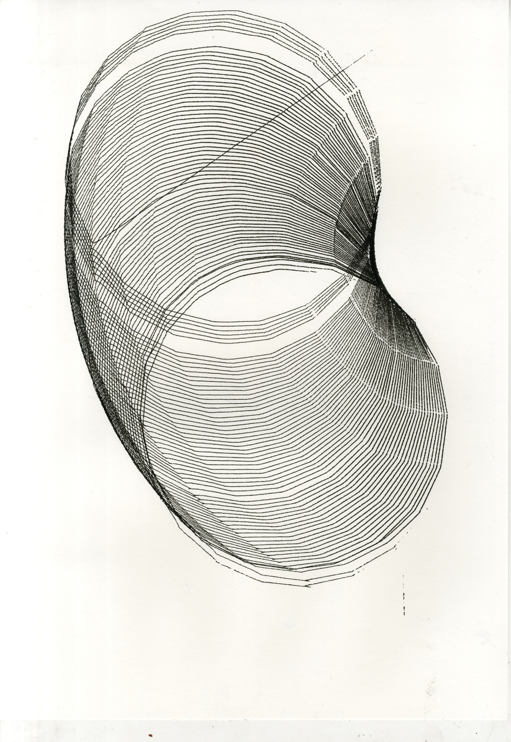
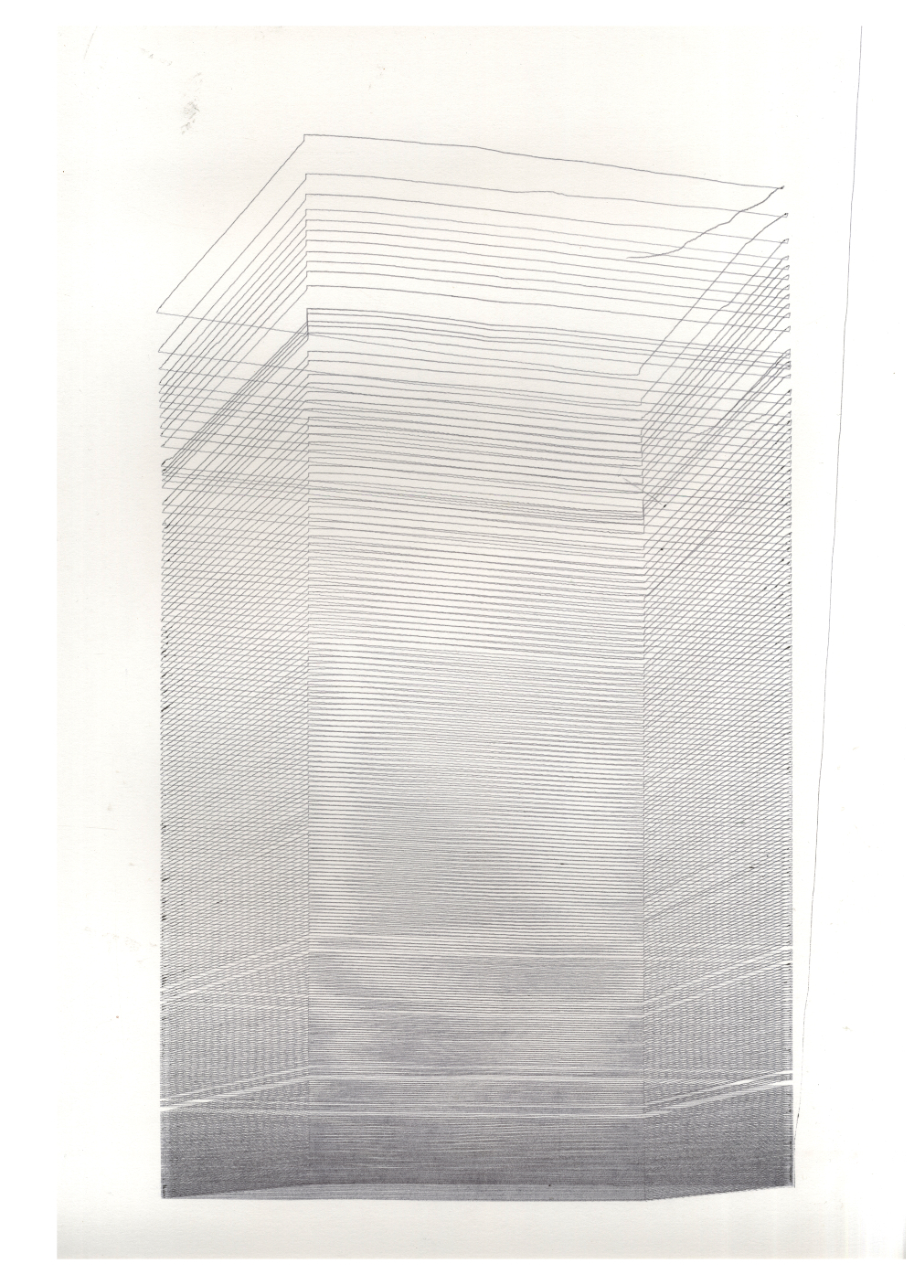
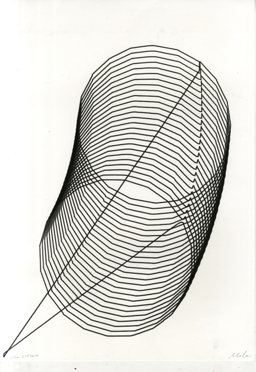
- I'm interested in using 3d imagery to feed the machine - maybe topographic maps or line renderings of 3d objects. A lot of the repetition drawings I've been making are already going in this diretion.
In other news, the missing shaft support is finally on the way. It should help make the machine more stable, maybe solve some of the issues with the y-axis getting stuck.
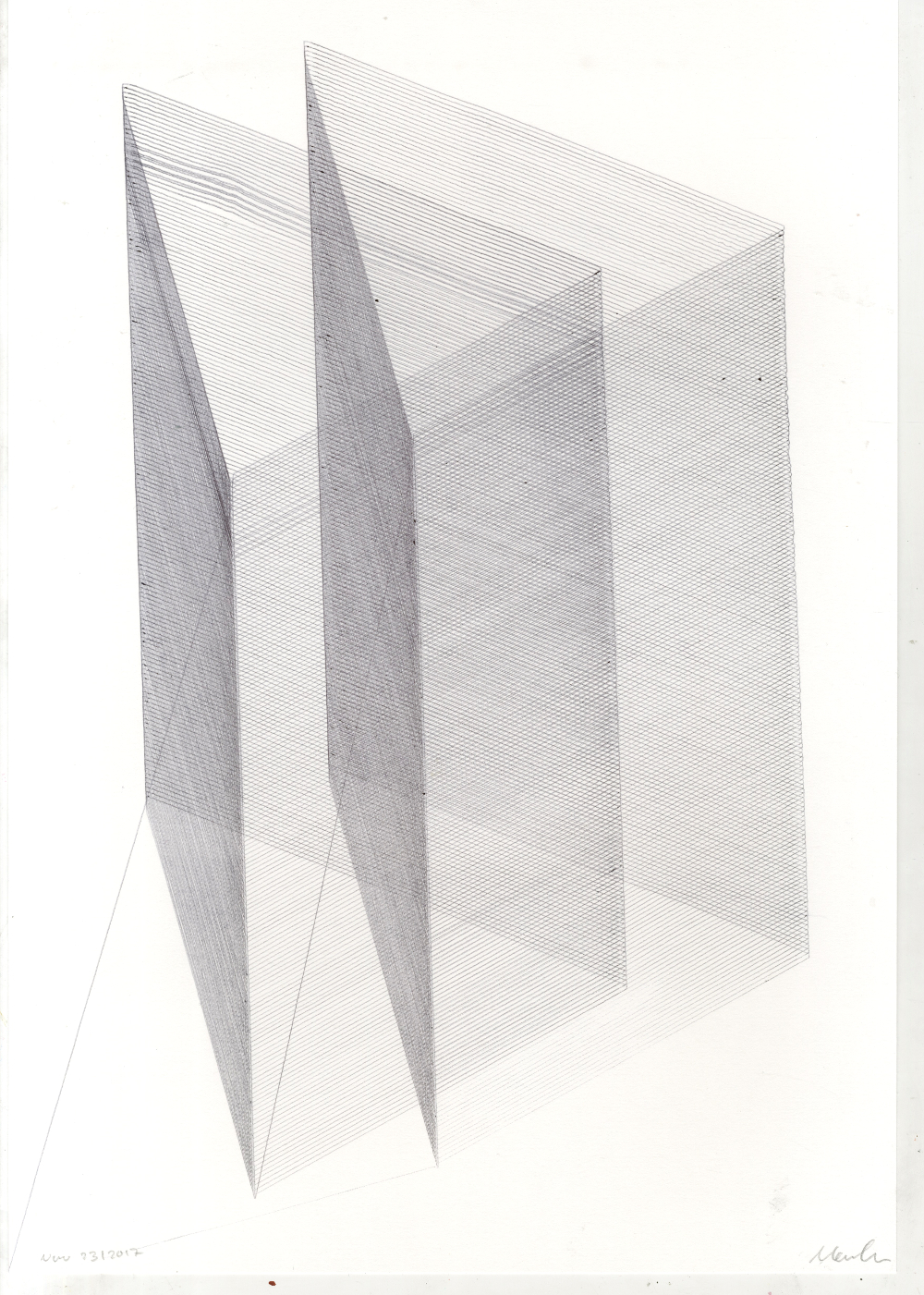
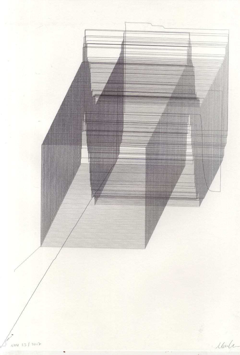
November 25, 2017
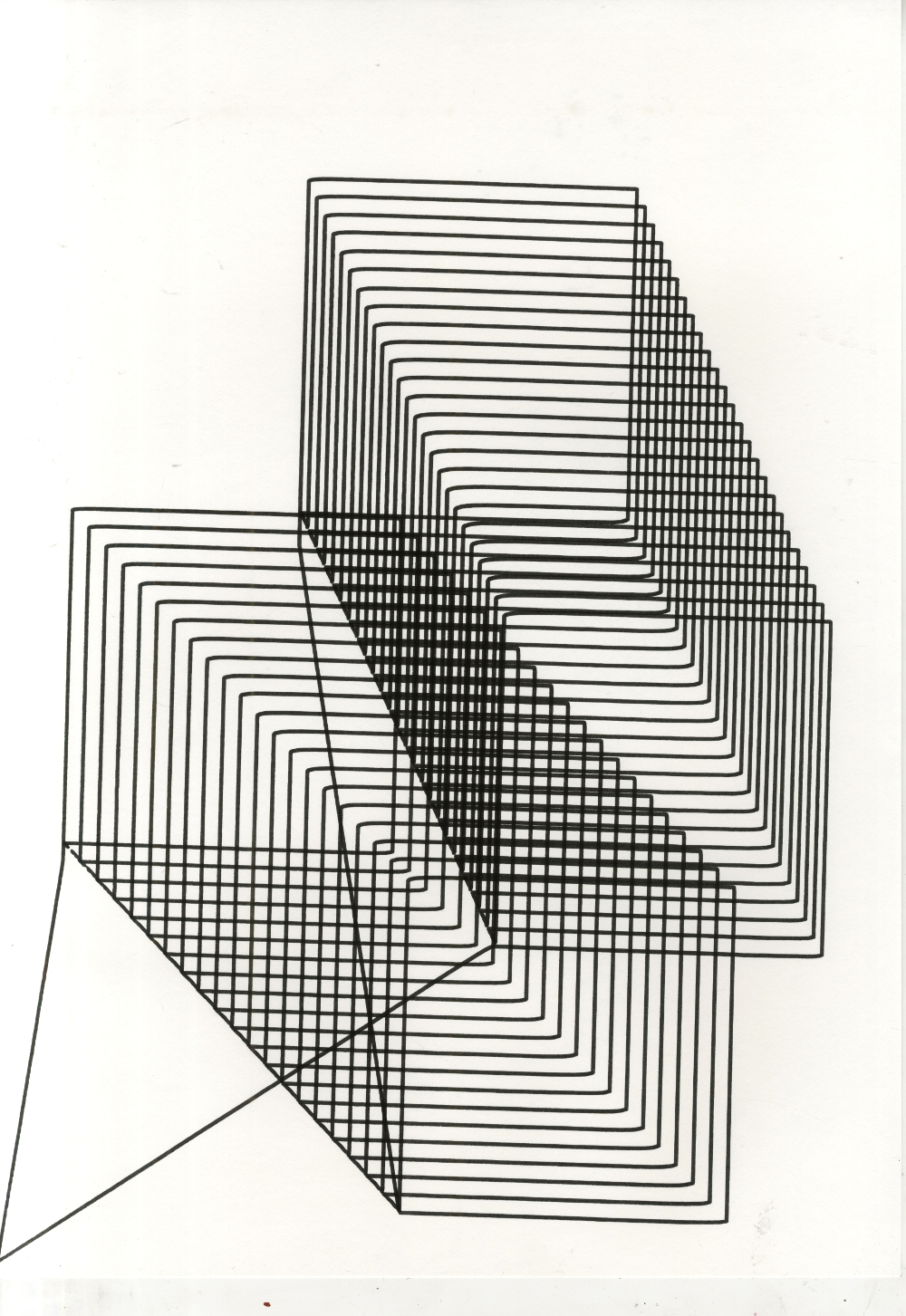
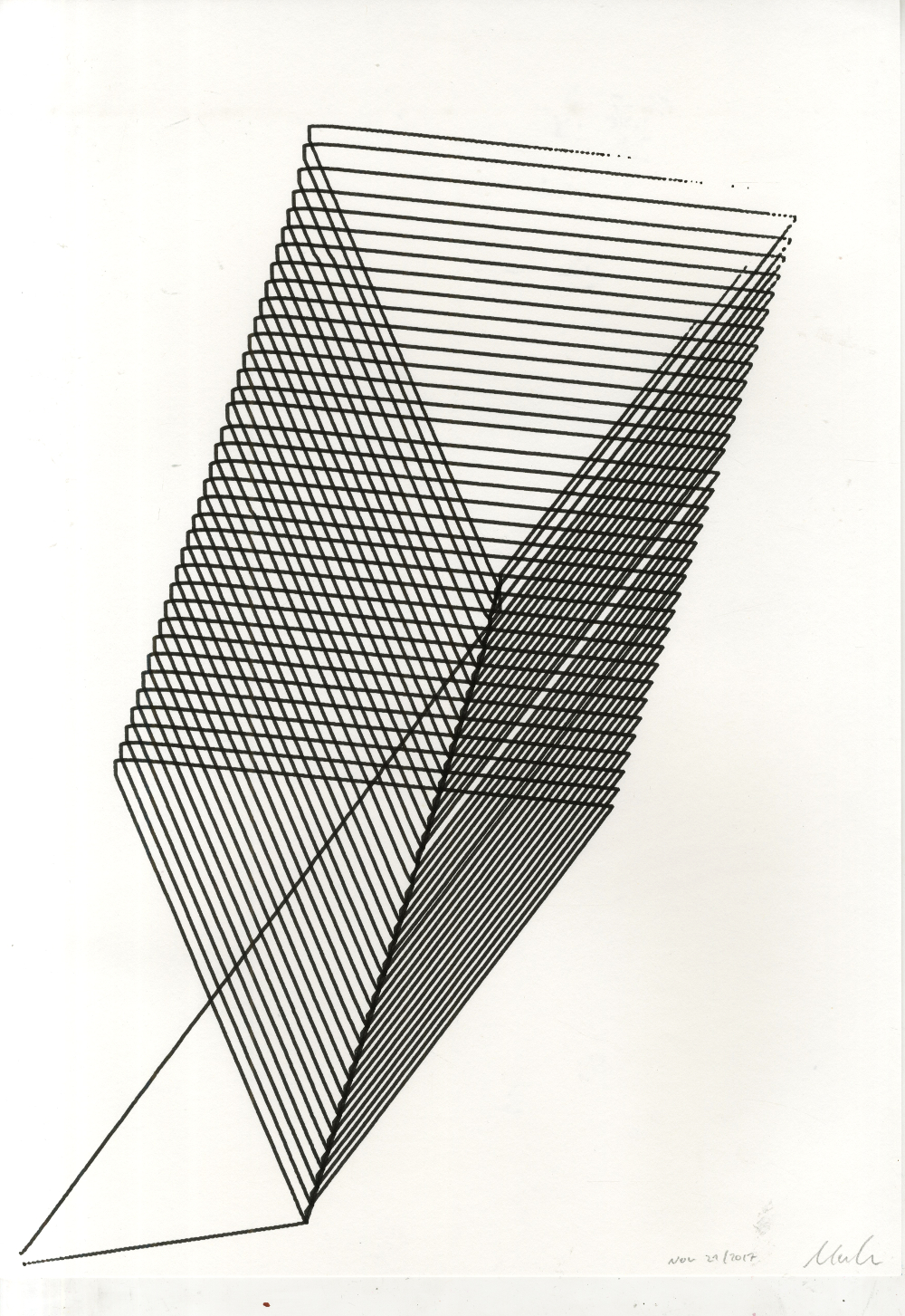
Here's some of the images I made on the drawing machine this week. Most of were designed in Illustrator, with any randomness coming only through the machine itself (by it getting stuck, someone bumbping into it, teh pen running out of paper etc.)
December 20, 2017
TODO instagram images
January 19, 2018
Emma suggests I look at Wind Drawings by Cameron Robbins. As he describes it,
The Wind Drawing Machines are installed in different locations to receive weather energy and translate it into an abstract format of ink drawings on paper. [...] The machines respond to wind speed and wind direction, and allow rain and sun to also play on the drawings. The principle employed here is that the wind direction orients a swiveling drawing board connected to a wind vane, while the wind speed drives a pen on a wire arm around in a cyclical motion.
I like the notion that these are abstract drawings, but also in some sense a very accurate record of a specific place at a certain time. Similar maybe to Sam Winston's work. The first thing I thought of was doing something with Met Office Data, but that seems contrived.
January 24, 2018
TODO Random pixel shading
January 25, 2018
TODO Random pixel shading layering
January 26, 2018
I managed to source some CMYK ballpoints. Unfortunately, they only come in a pack of 20 together with 4 other colours that are less useful. Here's the first four-colour drawing I did, using the randomized pixel method:
Here's one using regular pixels, using [this Warhol print] (Primarily because it has bright colours, secondly because it continues the tradition of using communist leaders as test subjects):
I prefer the second one a lot. Each pixel is inked much more evenly, leading to cleaner colours. The square pixels also make it easier to align each layer, although getting it perfect seems pretty difficult. I did, however, run this drawing at quarter step to save time, so there should be room for improvement if I'm willing to wait twice as long. Having developed this method of layering colours on top of each other, I'm now effectively screenprinting (as opposed to doing line drawings).
Some more insights from this test:
- As with earlier layered drawings, it's best to reduce the density of each layer. Otherwise you end up with thick blotches of ink with no added detail. This has the added benefit of speeding up drawing time.
- I printed CMYK in that order because that's how it's done in normal printing.
- As Jake points out, the colour mixing in CMYK comes from a combination of overprinting and optical mixing. In the above test, the colours seem to be pretty accurate.
January 28, 2018: Another Drawing Machine
Over the weeked I made the decision to build another drawing machine. I've been struggling for ages to find some sort of "interactive mode" for the original drawing machine. I tried building some sort of shape recognition software that would allow you to draw shapes and have the machine interpret them. I also talked about building a language-processing system that would allow people to write Sol Lewitt-style instructions and have the machine interpret them. None of that seemed too promising.
So the solution is to build a second drawing machine, one that is designed to be an interactive installation. It's going to look something like this:
TODO add sketch
The plan is to have it done by the Friday.
I've already written some of the control code. I'm using socket.io to display the function graphs in real time.
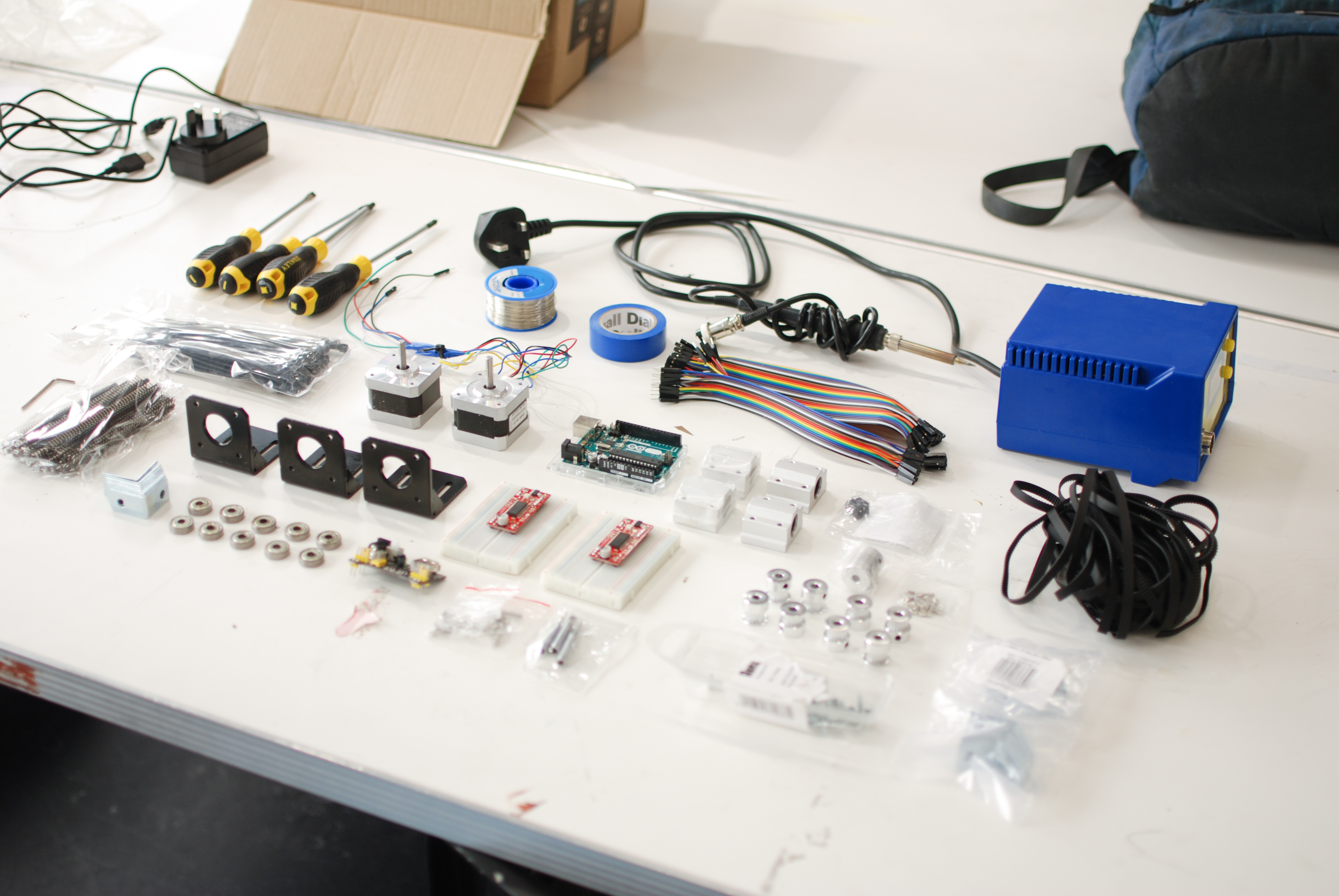
I'll need the following parts:
- 2x NEMA 17 Stepper
- 2x NEMA 17 mounting bracket
- 2x Stepper Driver (Easydriver)
- 12V Power supply
- Breadboard barrel jack
- 6x Potentiometer (ie. knobs)
- 10x Binary Switch
- Jumper wire
- Breadboards
- Arduino Uno (Another One)
- A wooden plank to mount everything on
- A wooden board to become the control panel
- Fishing line
- Various fixings
Things I'm not sure about yet:
- How do I mount a pen to the thing?
- How do I attach the fishing line to the motor shafts?
- How do I attach the drawing machine to the wall in such a way that the pen is in contact with the paper?
Using Wikipedia, I managed to cobble together the following functions to generate sine, triangle, sawtooth and square waves that will eventually control the motors. $$a$$ is the amplitude, $$p$$ is the period, $$o$$ moves the curve up and down and $$\varphi$$ moves the curve from left to right (I'm using this to animate it on screen).
$$\DeclareMathOperator{\sgn}{sgn}$$ $$\DeclareMathOperator{\atan}{atan}$$ $$\DeclareMathOperator{\asin}{asin}$$ $$\DeclareMathOperator{\cotan}{cotan}$$
Sine: $$f(x) = a\sin(2\pi px + \varphi) + o$$
Square: $$f(x) = a\sgn\big[\sin(2\pi px + \varphi)\big] + o$$
Triangle: $$f(x) = a\arcsin\big[\sin(\frac{2\pi}{p}x + \varphi)\big] + o$$
Sawtooth: $$f(x) = \frac{-2a}{\pi}\arctan\big[\cot(\frac{x\pi+\varphi}{2p})\big] + o$$
January 29, 2018
I've started construction on the second drawing machine. I'm using a wooden clipboard from the college art shop for the control panel - seems appropriately haphazard. Apparently I'm the first person to ever buy one of these in the art shop - it took them about 5 minutes to find the price in the register.
I drilled holes to mount six potentiometers and wired them to the Arduino's analogue inputs:
Then I plugged their readings into the code for the sine functions, and to my amazement it worked on the first try. You can twist the knobs and watch the curves on the screen change in real time. Insert mad scientist laughter here. There seems to be some interference between some of the potentiometers - manipulating one changes the readings of other ones in the series. Apparently this is because some of them have too much resistance. I'll replace and see if that's fixes it.
Peer assesment
TODO make the 100 drawings book publication
January 31, 2018
The flip switches for drawing machine two arrived. I'm planning to use these to
- Switch between different functions for each stepper
- Toggle some sort of randomisation for each funtion parameter on each stepper
I'm focussing on one for the moment. Since there are four functions to choose from, I can combine two switches to generate four possible positions by thinking of each switch as a digit in a binary number:
| Switch A | Switch B | Binary | Result |
|---|---|---|---|
| Open | Open | 00 | Sine |
| Open | Closed | 01 | Triangle |
| Closed | Open | 10 | Square |
| Closed | Closed | 11 | Sawtooth |
Febuary 1, 2018
Got the second drawing machine working today:
I found out that to draw a circle (and similar shapes), the two functions need to be on different phases - otherwise you just get straight lines. At the moment I'm doing this by adding a hard coded number to $$\varphi$$, but that's not the best solution. I can't just add another knob because there are no analogue inputs left on the Arduino. However, I could add another switch to add a secondary function to the "offset" knobs.
This will make the machine needlessly complicated and more annoying to use. So I'm definitely doing it. Problems:
- It runs pretty slow (but switching to quarter- or half stepping should fix that)
- There is quite a bit of noise because the motors always run at full speed, coming to a sudden stop (I assume while math is being executed) and running at full speed again. A possible fix might be to run the motors slower when there is less space to cover - this way each "movement section" would be equal in length, which would at least make the noise more uniform. A different type of string (ie. fishing wire) might also help.
- The pencil might not be the best drawing instrument to use here. While I like the hazy, out-of-focus shapes it creates, it doesn't produce results quickly enough for a possible gallery installation. I'll try out some different pens and felt-tips, as well as a softer pencil and charcoal.
- You can't make a shape the size of the paper at the moment. This should just be a matter of tweaking this line in the control script.
Febuary 9, 2018
A new plan for action
Following the mid-term review with Tracey and conversations with various people.
The drawing machine project needs a point. I think the point is the following:
- When I was doing the first set of drawings back in November, I was drawn to the ones where the lines start creating grey values - essentially where the drawing starts to move away from being a mathematical line diagram and towards being something more human.
- That's why I started doing
Book Structure
- Drawing machine progress (chronological)
- Background research
- Drawing machine progress
- Original research document
- Drawing machine progress
The machine learning publication could be in a similar format.